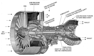
GAS TURBINE(AIRCRAFT ENGINE)
It is flow cycle engine. Air is compressed and heated by burning fuel after which it passes through the turbine which drive the comprssor and fan
Basically a gas turbine contain 2 section
i core section produce power to drive the propulsor section
ii Propulsor section that produce the thrust
Thrust is force created by the acceleration of air
Thrust = airflow x change in velocity
This is basically from newtons second law
Force = Mass x Acceleration(This force propelles the Aircraft)
Working Principle :
Intake of air in the low compressor It passes through the rotary blades in between stationary blade.
After it enter in to the high pressure compressor where the pressure raise to 70% at the end the of high pressure is 35 times high pressure and 1000° C hotter than outside air.
Air (air it is now in right pressure to ignited but it is moving too fast to efficient to ignited )leaves the compressor and passes through the diffuser where it converts the velocity energy into pressure energy and to remaining optimum temperature and pressure.
Total massive air passes through the combustion chamber is primary air and enter in to the flame tube (flame tube orifice) for combustion remaining air passes along the outside of the flame tubes entering through dilution holes in the side of the tubes and is used for cooling.
Each combustion chamber containing a burner containing swirl type atomizer. Through the atomizer fuel is injected under pressure by the fuel pump inside the combustion chamber . where the fuel is mixes the fine droplets incoming primary air. Combustion mixture is formed is ignited by the ignitors by 2 or 3 of the combustion chamber depends on the design of the engine .
On completion of the starting cycle ignitors are cut off at this stage we have “light off’
From this point combustion is continuous and pressure inside the combustion chamber for the given fuel flow is constant .
Residual of the secondary air which passes through the dilution hole in to the flame tube mixes with the main massive burning gas and cools it sufficient committed to pass through the turbine at a temperature with the safe limits of the turbine material with in the combustion chamber . going to the added heat energy fuel the gas rises in temperature and increases in volume
After the hot gases pass through the combustion chamber hot gasses enter into the nozzle guide ways which direct them increases the velocity on to the turbine blades. Causing the turbine disc to rotate. Which turn drives the compressor of the total energy approximately 60% is used to drive the compressor so that it is considerable drop in gas.
Remaining 40% of energy after deriving the turbine and the compressor used to form high speed
Jet which has substancely residual pressure this jet passes exhaust cone to merge at the cluster atmospheric pressure at the orifice.
Jet not only produce the kinetic energy going to its velocity but also has heat energy
Heat energy released to atmosphere and consequently wasted
This heat energy which is wasted to the atmosphere is more than 800° C this heat can be used in some other way to some useful energy for the aircraft
Three main condition in the engine working condition
i During Compression work is done to increase the pressure & decrease
the volume of air which will corresponding increase in the temperature.
ii During the Combustion when fuel is added to the air and burned to increase
the temperature there is corresponding increases in volume while the
pressure remains almost constant.
iii During the expansion when work is taken from the gas stream by the turbine
assembly there is decrease in temperature and pressure with corresponding
increase in volume.
OVERALL EFFICIENCY= (Propulsive Power (or) Thrust Power)/(Power Input To the Engine)
Propulsive Power = Mass of Air Fuel mixture[speed of existing gas from the engine - flight speed]
flight speed
Power Input To The engine = Mass flow of Fuel x Calorific Value of Fuel
(OR)OVERALL EFFICIENCY = Propulsive Efficiency x Thermal Efficiency
COMPARISON OF GAS TURBINE AND IC ENGINE
Arrangement of internal parts , pressure and temperature at various point of JT8D Engine(Pratt & Whitney)
Exploded view of the GE80C2 high bypass turbofan engine
Gas Turbine Engines - Fan Blades
Big Giants in the Evolution of Gas Turbine
HONDA Makes light engine for small aircraft
HF120 ENGINE FOR LIGHT JET ENGINE-GE & HONDA COLLABORATION MAKE
NEW INVENTION WITH TURBINE
INVENTOR
Sir Frank Whittle (1907–1996) was an English aeronautical engineer who invented the turbojet engine in 1930 (the first application of the gas turbine to jet propulsion).


